
This is an old revision of the document!
Introduction
These instructions do not purport to cover all details or variations of the product and do not claim to provide for every possible contingency in connection with installation, operation, or maintenance. Self-repairs performed by the customer may lead to damage or loss of your product. Should further information be desired or should particular problems arise which are not covered sufficiently or if repair services are desired, please contact The Tail Company (contact@thetailcompany.com).
For the purposes of this manual, “left” and “right” references will refer to the EarGear's orientation when worn on the body, relative to the wearer. So, the “right” side is the side of the EarGear with the control board, and on the wearer’s right.
Case Screws
There are three Phillips-head self-tapping screws holding the case together for each ear.
Left Ear:

Right Ear:

Installing Batteries
The EarGear Battery is a single 3.7V, 1200 mAh, 103040 (approximately 10 x 30 x 40 mm) LiPo battery with a “JST PH 2-pin” connector.
FAA rules on installed batteries are that devices containing lithium batteries (laptops, phones, and also ears) can be checked, but carry-on is preferred to prevent damage/fire. There is a battery capacity limit generally allowing capacities under 100 Wh. The ears, with a single 4.44 Wh battery, is well under the device capacity limits. Travel rules and restrictions should be reviewed in advance, but the Tail Co devices fall well under realistic limits being an “installed, non-removable battery” and a very modest capacity that should be acceptable anywhere a cellphone or laptop would.
The positive lead for the batteries is oriented to the left for J1.
The plug can be difficult to remove from the board. It’s suggested to pull out and slightly down towards the board (somewhat of a slight rolling motion) helps the plug release better, instead of pulling straight back.
Be aware that, although the JST-PH 2.0 connectors used on the batteries and across industry are polarized, the polarity that any one battery is set up for is EXTREMELY RANDOM. Positive and negative should be correctly indicated by red and black wires, but the position of the wires in the connector may not be correct for the MiTail (or whatever device you plan on using the battery in), because there's actually no real standard. Plugging in the battery with the polarity reversed can, depending on a lot of factors, be quite bad for the device and/or battery.
Installing Servos
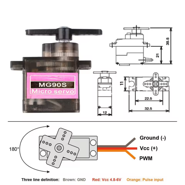
The Ears use two MG90S-equivalent 180 Degrees 1.8KG digital (PWM, not serial) servos. They are 4.5-6.4VDC standard hobby servos.
Internally, the firmware refers to the servos as Servo 1 (the “right ear” servo) and Servo 2 (the “left ear” servo). On the controller board connector, the top (away from the board) servo is the one on the controller board side (i.e., Servo 1/Right Ear). The battery side servo is the one closest to the board (i.e., Servo 2/Left Ear).
The visible shiny edge of the servo connectors go up (facing the viewer, away from the PCB):
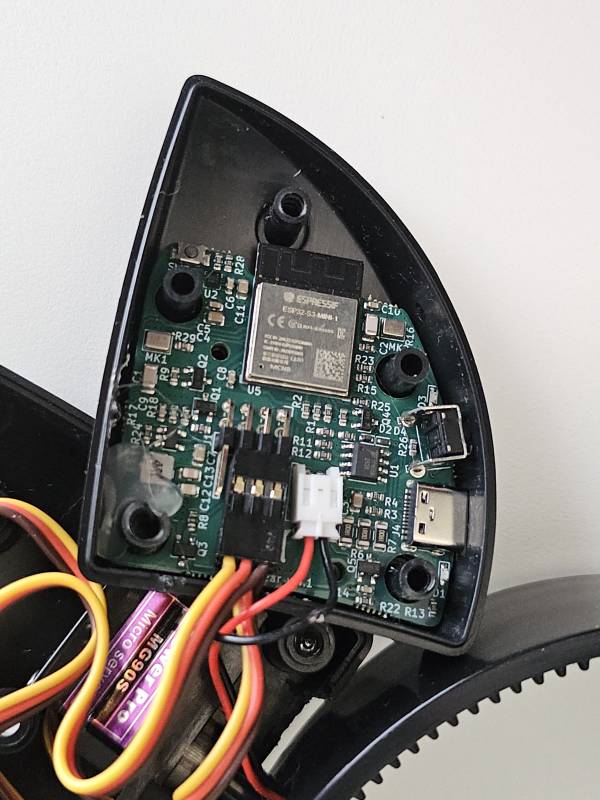
Avoid connecting the servos to the pins on the left end of the header block. These pins are not connected.
Make sure you have no slack pinched between the band and the body of the ears, most of the excess cable goes up in the ear case.
Servo Calibration / Resetting Servo Home Position
The servos need to be attached in their home position. To do this correctly, first power up the PCB with the new servo attached directly to the board. That will center or “home” the servo before you reattach the servo. The ear “home” position is the ears are parallel with the band. Ear position may be offset if desired, keeping in mind that the “home” position is the middle of the ear's range of motion.
Custom Mounting Servos
The servos use a 20T spline (25T is another, different spline that is common to encounter in hobby servos). The center screw is M2.5. Make sure your mount keeps the bottom of the ear casing free of obstructions, and that cables are arranged so that they do not resist the turning motion or pinch.
Notes about Tilt Mode
In order to prevent erratic and constant movement of the ears while Tilt Mode is enabled, there is a reset and cooldown timer. The way it works is once the ears move out of the “dead zone,” which is 14° off of center, the associated move is played. Once the ears have returned to the dead zone a 3000 ms (3 sec) cooldown is started. Once that timer has expired, the tilt triggers are re-enabled ON A TILT THAT STARTS FROM THE DEAD ZONE:
[xx:xx:03]INFO recvWithEndMarker(): COM value: 'TILTMODE'.
[xx:xx:03]OK
[xx:xx:03]TILT BACKWARD
[xx:xx:03]INFO setMove(): new command 'TAILHA'.
[xx:xx:03]TAILHA BEGIN
[xx:xx:07]INFO updateMove(): Cycle 0 move patterns complete.
[xx:xx:07]All pattern cycles complete.
[xx:xx:07]INFO updateMove(): Move sequence complete (3419 ms).
[xx:xx:07]Move sequence complete (3419 ms).
[xx:xx:08]Tilt cooldown countdown: 3000 ms.
[xx:xx:09]Tilt cooldown countdown: 2500 ms.
[xx:xx:09]Tilt cooldown countdown: 2000 ms.
[xx:xx:10]Tilt cooldown countdown: 1500 ms.
[xx:xx:10]Tilt cooldown countdown: 1000 ms.
[xx:xx:11]Tilt cooldown countdown: 500 ms.
[xx:xx:11]Tilt cooldown ended.
[xx:xx:11]Returned to center, tilt holdoff released.
So again, the tilt sequence is:
- Trigger tilt by tilting ears 14° off-center, front, back, left, or right.
- Return ears to center.
- Wait 3000 ms.
- Ears MUST return to center, if they are not there when the timer expires.
- Ears will trigger again if moved 14° off-center.